JUNIOR DESIGN POWER SUPPLY
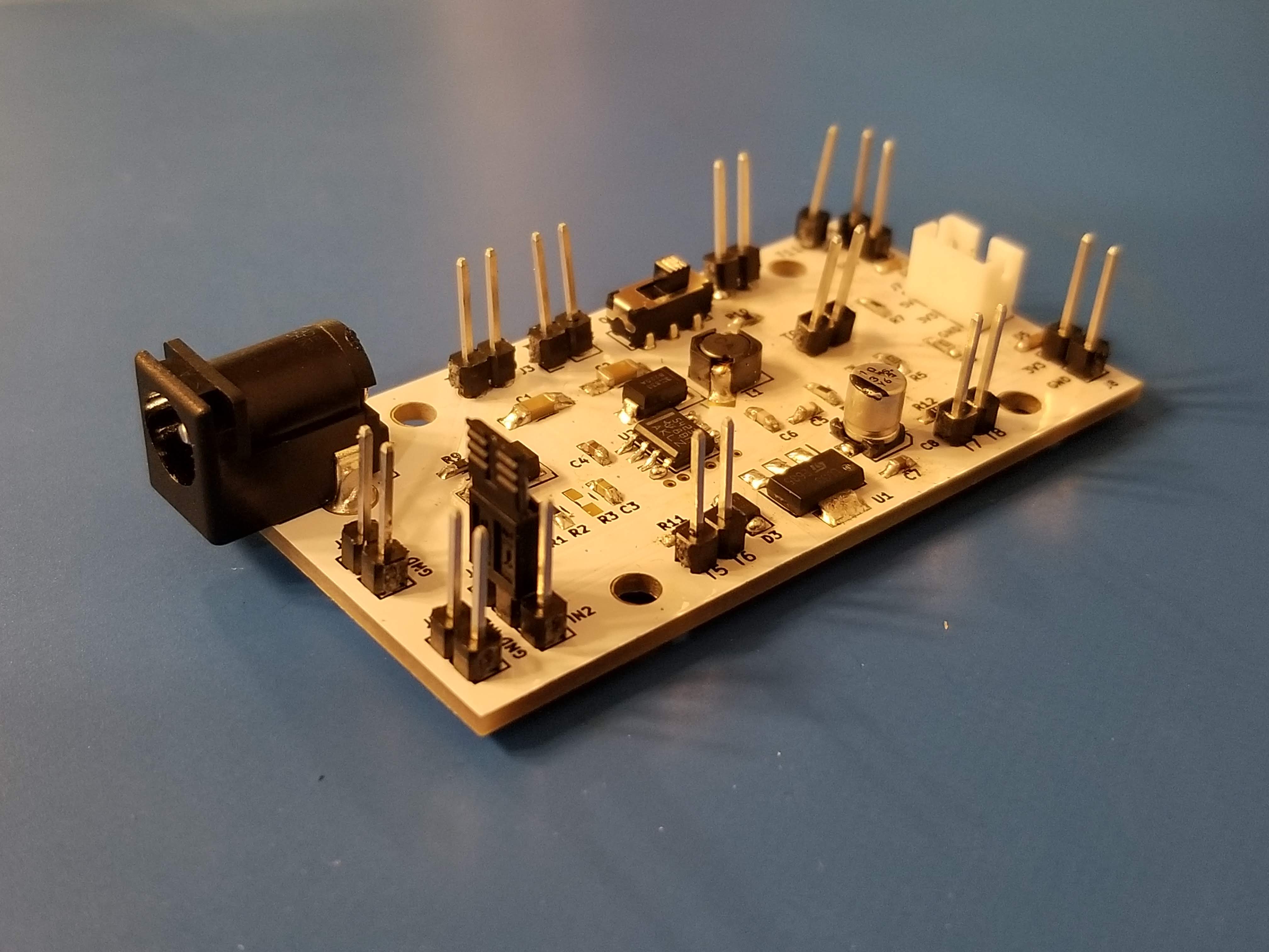
This project came from an assignment for ECE 341: Junior Design at Oregon State University. The project included assembling a SMD power supply with parts in the size range of 0603. Students were given the option of going into the electrical lab office hours to be given solder paste and have the Teaching Assistant (TA) cook the boards in the reflow oven. While that would have been fine, I’ve been though that process. I wanted to try something a bit trickier, so I used the reflow station that I keep on my desk and got to work with some standard 0.4mm tin-lead solder (63/37, always 63/37). Reflowing wasn’t too difficult after the first few components. The solder sticks so well to the parts once it gets up to temp. The only difficulty that arose was I had put the aluminum drum capacitor (one of those Panasonic package type) on the board too early. Causing it to get multiple waves of heat and causing the capacitor to eventually burst and go flying! Hit me square in the temple. Would recommend putting that piece on later in the process.
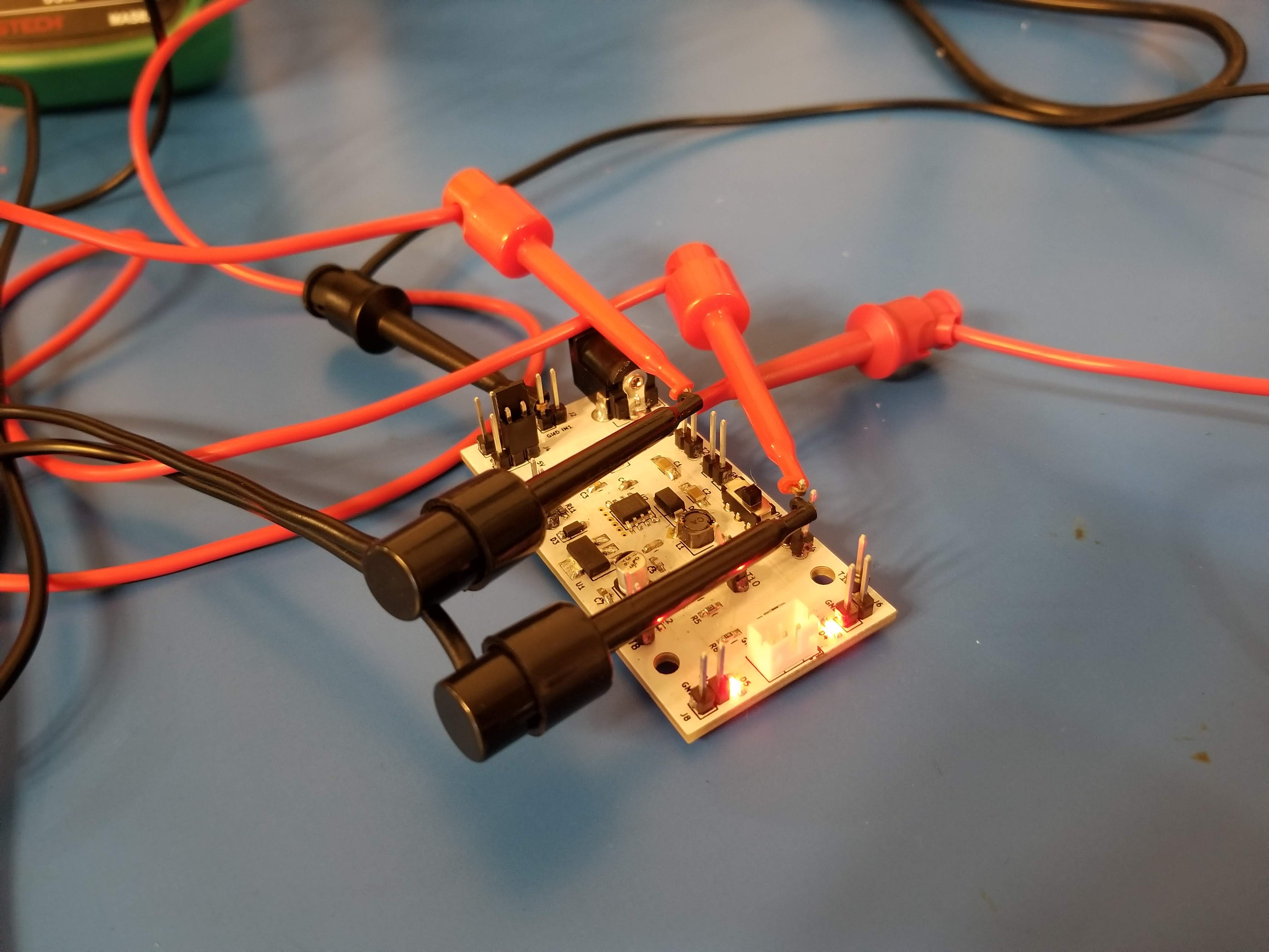
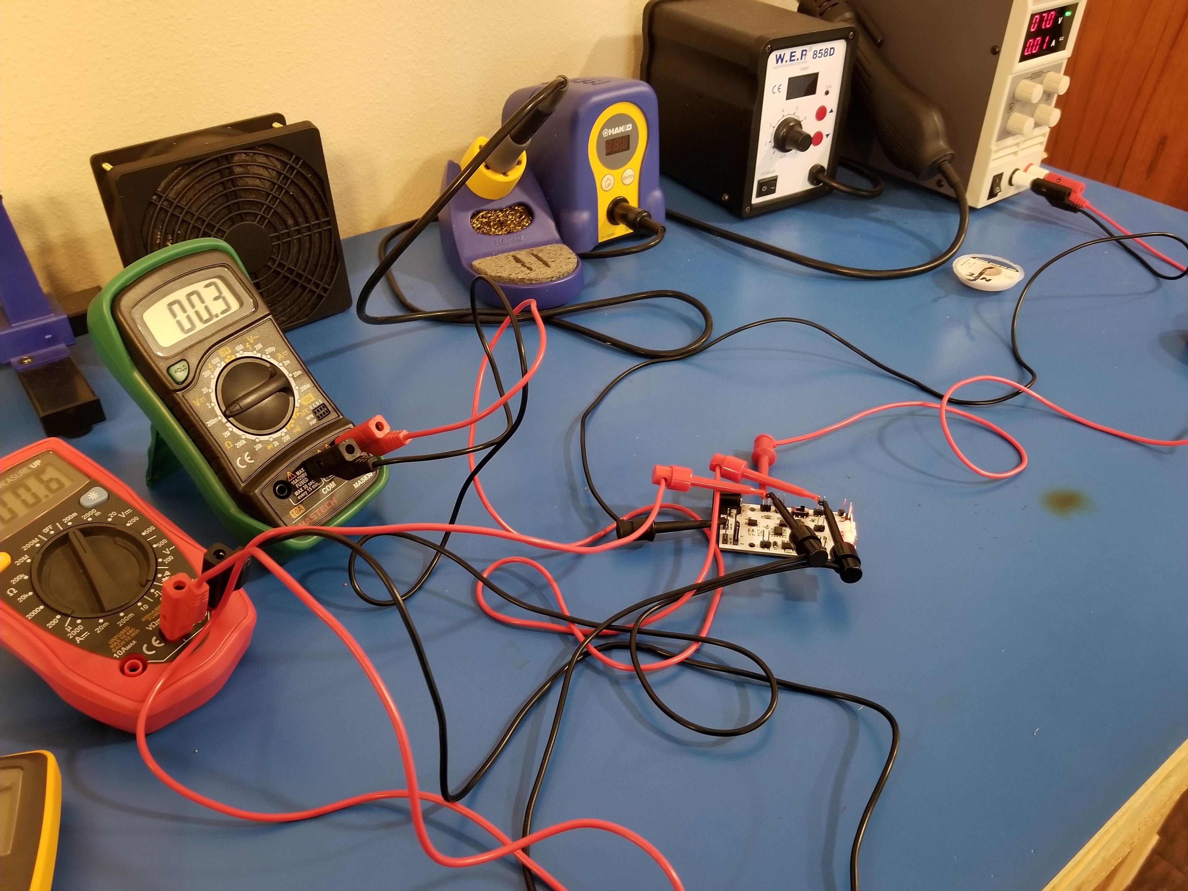
Once the SMD part of the board was assembled using the enclosed parts I finished the rest of with a just a soldering iron. This included the larger components like the DC Barrel Jack connector and the header pins. With the whole board done it was time for testing the two types of power supplies on the boards. There is a 5V switch-mode power supply that uses the Texas Instruments TPS54232 and a 3.3V linear power supply that uses a generic LD1117533TR. Measurements were taken on efficiency and voltage ripple.
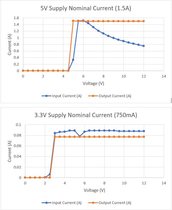
Efficiency Measurements
The Switching 5V Supply has much greater efficiency than the Linear 3.3V supply. For nominal currents the 5V supply had near perfect (>90%) efficiency, but the switching supply dropped off in efficiency as the change in voltage (between input supply and regulated supply) became greater. A Linear supply makes sense when power efficiency is not of great concern for your circuit (e.g. avionics systems that have electricity generated from the propellers of the aircraft). A 5V switching power supply would be a better option for a system that needs regulator efficiency (See supporting data below).
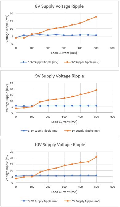
Voltage Ripple Measurements
For the 3.3V supply there was very little voltage ripple, regardless of the input voltage. The 5V supply has large relative voltage ripple compared to the linear supply. As the input voltage increased for the 5V supply the voltage ripple increased as well (See supporting data below).
The schematic for this board is available below along with the bill of materials for everything on the board. Thank you for reading!
Schematic Download
Here's the Bill Of Materials for this project
| BOM Item # | Item Name | Quantity | Price/Unit | Total Cost |
|---|---|---|---|---|
| 1 | PCB Manufacturing | 1 | $10.00 | |
| 2 | 4.9mmx4.9mm 3.3µH Inductor | 1 | $0.05 | |
| 3 | 3.5MM DC Barrel Connector | 1 | $0.50 | |
| 4 | B220 Schottky Diode | 2 | $0.50 | |
| 5 | 1N5819 SOD-12 | 1 | $0.50 | |
| 6 | 0603 LED | 2 | $0.75 | |
| 7 | 40ct. Male Header Pins | 1 | $1.00 | |
| 8 | 0.015µF 0603 Capacitor | 1 | $0.01 | |
| 9 | 0.1µF 0603 Capacitor | 2 | $0.01 | |
| 10 | 10µF 0603 Capacitor | 2 | $0.01 | |
| 11 | 10µF Panasonic D 4.0mm Capacitor | 1 | $0.40 | |
| 12 | 47pF 0603 Capacitor | 1 | $0.01 | |
| 13 | 680pF 0603 Capacitor | 1 | $0.01 | |
| 14 | 0.01Ω Resistor | 2 | $0.01 | |
| 15 | 0.05Ω Resistor | 2 | $0.01 | |
| 16 | 1.37kΩ Resistor | 1 | $0.01 | |
| 17 | 1.87kΩ Resistor | 1 | $0.01 | |
| 17 | 10kΩ Resistor | 1 | $0.01 | |
| 18 | 150kΩ Resistor | 1 | $0.01 | |
| 19 | 17.4kΩ Resistor | 1 | $0.01 | |
| 20 | 48.7kΩ Resistor | 1 | $0.01 | |
| 21 | 560Ω Resistor | 1 | $0.01 | |
| 22 | SPDT Switch | 1 | $1.00 | |
| 23 | LD1117S33TR | 1 | $0.50 | |
| 24 | TPS54232 | 1 | $1.50 | |
| $17.13 |